Environmental Barriers
At CF Group we have an extensive inventory of ground engineering plant and equipment meaning our team is qualified and able to install all methods of environmental barriers construction.
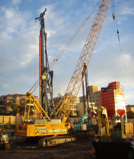
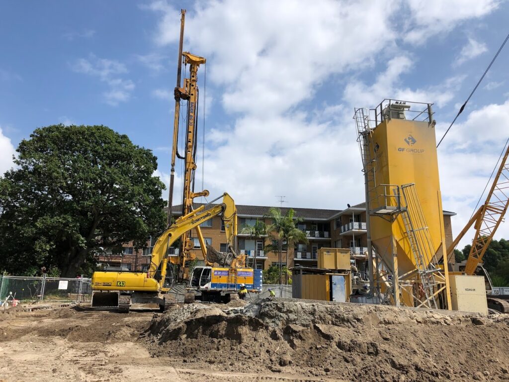
At CF Group we have an extensive inventory of ground engineering plant and equipment meaning our team is qualified and able to install all methods of environmental barriers construction.


CF Group is equipped to install the Soil Bentonite cut-off barriers with its range of hydraulic excavators available for trench excavation as well as backfill preparation and placement.
Soil Bentonite environmental barriers are constructed by excavating a trench under a bentonite suspension which provides stability to the trench excavation. The barrier excavation continues to a depth where it is keyed into a natural impermeable stratum, either a clay or rock layer at its base.
The trench excavation is executed by means of a hydraulic excavator, for deeper trenches purpose made long arms are fitted to the base machine and for trenches with depths beyond the reach of the long arm excavator a clamshell is used to extend the trench depth to the design level.
The excavated spoil is deposited parallel to the trench or, where insufficient space is available adjacent to the trench, to a remote location, for mixing and blending into a suitably impermeable backfill material, which is then placed into the trench displacing and replacing the stabilising bentonite fluid. This backfilling operation follows behind the advancing trench excavation.
Cut-off barriers constructed by the Soil Bentonite technique can be expected to achieve permeability levels of 10-9m/sec
Bentonite Cement barrier is a long established method for the installation of hydraulic cut-offs.
CF Group is well equipped with its fleet of hydraulic excavators for trench excavation and automated material batch plants for slurry preparation.
Bentonite Cement barriers are constructed by excavating a trench under a bentonite cement slurry which provides stability to the trench excavation. The barrier excavation continues to a depth where it is keyed into a natural impermeable stratum, either a clay or rock layer at its base.
The trench excavation is executed by means of a hydraulic excavator, for deeper trenches purpose made long arms are fitted to the base machine and for trenches with depths beyond the reach of the long arm excavator a clamshell is used to extend the trench depth to the design level.
The excavated spoil is disposed of either on site or is trucked off site for dumping.
The bentonite cement slurry is designed to be self hardening and remains in the trench to perform the function of an impermeable barrier.
Cut-off barriers constructed by the Soil Bentonite technique can be expected to achieve permeability levels of 10-8m/sec
This style of wall has proven to be a natural fit for CF Group largely due to the advent and on-going development of the CSM wall system closely coinciding with the emergence of our presence in the geotechnical market.
Details of the system and its advantages are covered in detail under a separate primary heading; however, it is important to emphasis the value of this style of wall and its role as an impermeable barrier.
Following are listed relevant advantages of the system:
– A continuous barrier is created by overlapping the CSM panels.
– Precision of installation is achieved by the use of the monitoring systems.
– The in-situ soil remains a component of the finished product; therefore there is limited spoil to be removed.
– Production rates are comparable to other methods of barrier installation.
– Keying into rock is more readily achievable than with other methods.
– Barrier permeability is less than 10-8m/sec which is comparable with other methods of barrier construction.
CF Group owns a range of vibratory hammers commonly used for sheet pile installation which are ideally suited for application to VIB Walls.
Thin VIB Walls are installed by vibrating a steel mandrel into the ground and delivering the backfill slurry at the toe of the mandrel as it is withdrawn, the slurry filling the void created by the mandrel.
Frequently the mandrel comprises of an ‘I’ beam, modified at its base to create a thickening of the web to match the designed barrier width and at the top to allow it to accommodate the energy imparted by the driving vibrator.
The mandrel is driven into and withdrawn from the ground progressively to form a continuous barrier, the rear flange of the mandrel matching the position of the leading flange on the previous pass.
The slurry design includes cement and bentonite and in some cases fine aggregate is included in the mix.
Not only are VIB walls very cost effective, production rates are high and the permeability increase due to the width of the barrier can usually be compensated for by appropriate slurry design.
Deep Drainage Trenches are essentially an extension of the slurry cut-off barrier methodology, where, instead of installing an impermeable barrier, a permeable collection barrier is installed.
Excavation of the collection trench is most commonly undertaken by hydraulic excavator and the trench support during excavation is provided by a Bio Polymer solution.
CF Group’s inventory of hydraulic excavators gives it the ready capability for drainage trench installation.
The drainage trench is excavated through the Bio Polymer solution to the design depth as a continuous trench; once the trench excavation has progressed an adequate distance from the starting point to be clear of the toe of the slope of the backfilling operation, backfilling can commence. Backfilling comprises the placement of a design graded sand which progressively follows the excavation of the trench.
At the completion of the backfilling operation the backfilled trench contains Bio Polymer in the pore spaces between the sand particles which needs to be degraded.
This activity is achieved by the installation of a series of wells, left in the trench at regular intervals during the backfilling process, which facilitates the circulation of the Bio Polymer from the backfill back into the trench; this in concert with the addition of pool chlorine effects the degrading of the Bio Polymer.
This style of barrier is an extension of the Deep Drainage Trench technique also available from CF Group. In this version however, the barrier is installed to intercept the flow of a plume of contaminated ground water
The trench is excavated under the same methods as the Deep Drainage Trench; the point of difference is the nature of the backfill material.
The backfill material placed into the trench is a mixture of sand plus reactive agents designed to neutralise any contaminants carried by the ground water plume.
Funnel and Gate Barriers are formed by a combination of slurry trench techniques. These barriers are just another technique available through CF Group.
These barriers are designed as follows: An impermeable barrier is created to intercept a plume of contaminated ground water. There is a small gap left in the impermeable barrier and within this gap, a panel of deep drainage trench is excavated and backfilled with sand plus reactive material, designed to neutralise the plume contaminants.
The impermeable component of the barrier is used to direct and funnel the flow of the plume to the permeable gate making this style a particularly effective option in the appropriate circumstances.
Stabilisation of contaminated soil to prevent the spread of contamination by ground water carriage is a technique readily encompassed by CF Group. The group is able to utilise this technique thanks to its ownership of rare large capacity rotary drilling equipment.
The methodology involves treating the contaminated ground with overlapping passes of a large diameter (up to three metres) mixing auger over the depth of the contamination.
During the drilling and the mixing process, a binding or neutralising agent is introduced via the drill stem. It is then mixed into the contaminated soil.
Frequently the remediation is effected by using cement suspension as the binding agent to create a monolithic impermeable block of stabilised soil; however, to address some contaminants, neutralising agents may be preferred.
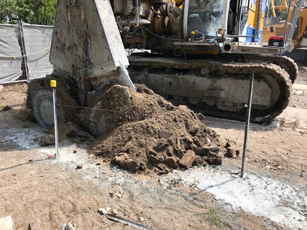
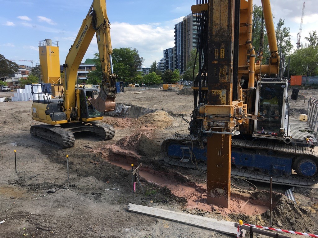
Environmental barriers are installed into the ground for the purpose of intercepting the transmission of ground water or as a means of collecting ground water. They are often also used to control the flow of ground water carrying contaminants.
For the purposes of arresting or redirecting ground water flows, low permeability barriers are employed while for the collection of leachates, deep drains are employed. Both are used to collect, treat and discharge water.
Barrier installation involves: either, the removal and replacement of the in-situ material or the incorporation of new material mixed into the soil in-situ.
For the removal and replacement options a trench is excavated, removing the in-situ soil, with the stability of the trench excavation being maintained by means of a fluid suspension of: bentonite for Soil Bentonite barriers, self hardening slurry for Bentonite Cement barriers and Bio Polymers for Deep Drains. The replacement (trench backfill) material comprises of: the excavated soil blended to a suitable grading for Soil Bentonite barriers, the hardened slurry for Bentonite Cement barriers and graded sand for Deep Drains.
Variations to the basic systems described above are available and CF Group is able to provide those too. For more details click on the specific type of work you’re interested in or contact us for more information.